
Online publication date 16 Sep 2026
Initial Design and Numerical Analysis of a Heat Exchanger Model for a Large-Capacity Offshore Wind Turbine Transformer

Copyright © 2026 by the New & Renewable Energy
This is an Open Access article distributed under the terms of the Creative Commons Attribution Non-Commercial License (http://creativecommons.org/licenses/by-nc/4.0) which permits unrestricted non-commercial use, distribution, and reproduction in any medium, provided the original work is properly cited.
Abstract
Effective thermal management is crucial for the reliable operation of large-capacity offshore wind turbine transformers, which operate under highly variable power loads and harsh marine environments. The adoption of natural-ester-based insulating oils improves fire safety and environmental compatibility. However, they introduce cooling challenges owing to their high viscosity and lower thermal conductivity compared with conventional mineral oils. This study presents a comprehensive three-dimensional computational fluid dynamics (CFD) framework, investigating a compact, fin-type ester oil–water heat exchanger operating under a counter-flow configuration. The numerical model considers fully conjugate heat transfer to evaluate temperature distributions, flow characteristics, and cooling effectiveness. Parametric investigations indicated that the water-to-oil mass flow rate ratio determined the overall cooling capacity. By contrast, the oil mass flow rate governed the outlet oil temperature through fluid residence time effects. Lower oil flow rates maximized temperature drops, whereas increasing the water mass flow rate reduced thermal returns once water-side convective resistance was minimized, stabilizing the outlet oil temperature at approximately 21°C. Higher oil inlet temperatures increased the thermal driving potential, resulting in progressive enthalpy drops of up to 130 kJ/kg at a 100°C inlet. These quantitative findings establish robust engineering guidelines for designing high-performance, energy-efficient cooling systems tailored to modern wind energy infrastructure.
Keywords:
Large scale offshore wind turbine, Transformer, Ester oil cooling, Heat exchanger, Thermal performance키워드:
초대형 해상풍력터빈, 변압기, Ester Oil 냉각, 열교환기, 열성능1. Introduction
The rapid expansion of renewable energy technologies has led to a significant increase in the deployment of onshore and offshore wind power plants. Wind power transformers are critical components in these systems, enabling voltage step-up from turbine generators to grid-level transmission networks. Unlike conventional grid transformers, wind power transformers operate under highly variable loading conditions caused by stochastic wind behavior, frequent start–stop cycles, and intermittent power generation. These challenges are exacerbated in offshore and nacelle-mounted installations, where space limitations, high humidity, salt-fog exposure, and limited cooling capability complicate thermal management.[1]
Thermal performance plays a decisive role in transformer reliability, efficiency, and service life. Elevated temperatures accelerate the thermal aging of cellulose insulation, degrade dielectric liquid properties, and increase the probability of insulation failure, leading to unplanned outages and high maintenance costs.[2,3] International standards, such as IEC 60076-7, explicitly identify temperature rise and thermal aging as dominant design constraints for oil-immersed power transformers operating under cyclic loading and overload conditions.[4] Consequently, developing compact, reliable, high-performance cooling systems is essential for modern wind energy infrastructure.
Traditional transformer cooling system design methods rely primarily on empirical correlations, lumped thermal networks, or simplified analytical models. While these approaches are useful for preliminary assessments, they are inherently limited in predicting localized hot spots, three-dimensional flow non-uniformities, and coupled fluid–solid heat transfer effects in compact exchangers.[5] These limitations become more pronounced when natural ester insulating oils are employed, as their higher viscosity and lower thermal conductivity significantly alter convective heat transfer behavior and pressure losses.[6~8]
Natural ester insulating oils are increasingly adopted due to their high fire and flash points, biodegradability, and reduced environmental impact.[7] However, their unfavorable thermal–hydraulic properties necessitate optimized heat exchanger designs. Fin-type heat exchangers, characterized by high surface-area-to-volume ratios, offer an effective way to enhance heat-transfer performance while maintaining compact dimensions.[9,10] Computational fluid dynamics (CFD) has emerged as a powerful tool for detailed analysis and optimization of thermal systems in power and energy engineering. CFD enables spatially resolved predictions of velocity, temperature, turbulence, and entropy generation, providing deeper insight into the physical mechanisms governing cooling performance.[11,12] Although CFD studies have been reported for transformer windings, cooling ducts, and radiator systems, comprehensive investigations focusing on compact ester oil–water heat exchangers specifically designed for large-scale wind power transformers remain limited.
The present study conducts a CFD-based thermal performance evaluation of a fin-type ester oil–water heat exchanger tailored for large-scale wind power transformer cooling, aiming to establish clear design guidelines for efficient and reliable operation.
2. Modeling and Methodology
2.1 Heat Exchanger Modeling
The cooling system investigated in this study consists of an external ester oil–water heat exchanger integrated into the oil-circulation loop of a large‑scale wind power transformer. External modular cooling units are preferred in offshore substations and nacelle‑mounted transformers because they offer compactness, installation flexibility, and ease of maintenance under constrained environmental conditions. A representative 9.2 MVA offshore wind turbine transformer using ester-based insulating fluid was selected. Based on typical manufacturer efficiency data, the total thermal loss, including core and winding losses at full load, is approximately 0.6% of the rated apparent power, corresponding to a required heat dissipation capacity of about 55.2 kW. In accordance with the thermal limits specified in IEC 60076-7, the cooling system must maintain acceptable top-oil and winding hotspot temperatures to ensure insulation reliability and prevent thermal aging.[4] Therefore, the proposed heat exchanger was designed to continuously dissipate the nominal thermal load of 55.2 kW while accommodating transient thermal peaks of up to 80 kW during periods of maximum power generation. The heat exchanger is designed as a compact fin‑type structure in which hot ester oil and cooling water flow through separate internal channels and exchange heat through thermally conductive solid walls. A counter‑flow configuration is adopted so that hot oil and cold water flow in opposite directions, maintaining a high local temperature difference along the heat exchanger and improving overall thermal effectiveness. The heat transfer process involves forced convection on both fluid sides and conduction through the separating wall, forming a fully conjugate heat transfer problem. Under steady‑state conditions, the heat transfer rate is expressed by Eq. (1). Figure 1 shows a schematic view of the heat transfer in the heat exchanger.
| (1) |
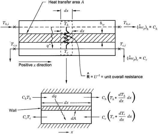
Schematic representation of heat transfer in the heat exchanger[13]
Natural ester oil is selected for its fire safety and environmental advantages, and its properties are shown in Table 1. However, its higher viscosity and lower thermal conductivity compared with mineral oil reduce convective heat transfer. The heat exchanger considered in this study is a rectangular channel designed to facilitate efficient heat transfer using ester oil as the working fluid. The channel has an overall length of 1210 mm, a width of 485 mm, and a thickness of 230 mm, providing a compact yet effective flow domain. Figure 2 shows the heat exchanger model with the oil and the water circulation pump. The oil flows through a circular pipe with a diameter of 40 mm, and the horizontal fins are mounted on the inner surfaces of the heat exchanger to enhance heat transfer between ester oil and water. Figure 3 shows the heat exchanger body and a cross-sectional view of the horizontal fin arrangement, which is made of SUS 304 stainless steel, with dimensions of 457 mm × 142 mm × 5 mm, attached to the heat exchanger wall. 60 fins with a spacing of 15 mm are attached to the heat exchanger wall. The inlet and outlet are positioned on opposite ends of the channel to ensure a uniform flow path. The conjugate heat transfer between oil, water, and finned surfaces is used to simulate a realistic heat dissipation scenario. This geometric configuration aims to maximize surface area for heat transfer while maintaining a manageable pressure drop, making it suitable for applications such as transformer cooling and renewable energy systems.

Physical property of ester oil[14]
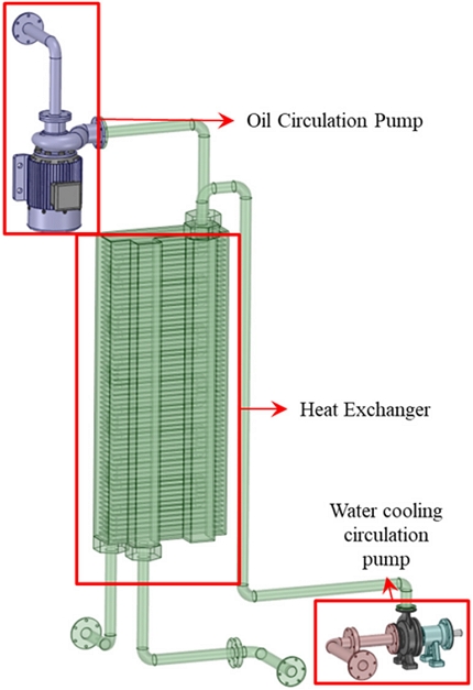
3D model of Heat Exchanger with oil and water circulation pump
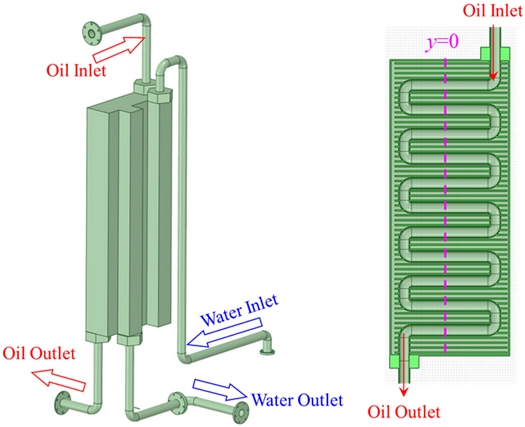
Heat exchanger with horizontal fins
2.2 Numerical Methodology
The thermal and hydraulic performance of the ester oil–water fin‑type heat exchanger is investigated using 3D steady‑state CFD simulations with fully conjugate heat transfer. The flow of ester oil and cooling water is modeled as incompressible and turbulent, and the Reynolds‑averaged Navier–Stokes equations are solved together with the energy equation in both fluid and solid domains. The adiabatic exterior wall with a contact thermal resistance of 10-3 m2.°C/W are used for the CFD analysis of the heat exchanger.[15] The thermophysical properties of ester oil and water are defined to capture realistic variations over the operating temperature range relevant to wind power transformer cooling. The turbulence effects are modeled using the shear stress transport (SST) model with an automatic wall function, which provides reliable predictions for internal flows with adverse pressure gradients and enhanced heat transfer surfaces such as finned channels. The computational domain includes oil passages, water passages, and solid fin structures, and a hybrid mesh with local refinement near walls and fins is employed to accurately resolve velocity and thermal boundary layers. The average y+ values for the oil pipe and heat exchanger body are less than 1 and 6, respectively. At the inlets, mass flow rate and temperature boundary conditions are prescribed for both oil and water, while static pressure conditions are imposed at the outlets. All walls satisfy no‑slip velocity conditions and are thermally coupled at fluid–solid interfaces. Figure 4 shows the fluid domain of the heat exchanger for CFD simulations.
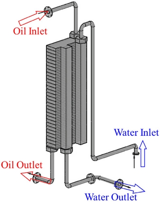
Numerical models for CFD analysis
The boundary conditions for the CFD analysis of the heat exchanger are shown in Table 2. The SST turbulence model was selected based on its proven ability to accurately predict internal flows with adverse pressure gradients and finned geometries. Unlike standard k-ε or k-ω models, SST combines near-wall accuracy with free-stream robustness, making it particularly suitable for compact heat exchanger simulations.[11] The simulation’s convergence is ensured by monitoring the residuals value of 10-6 and stabilization of outlet temperatures. A grid convergence study was performed using three mesh levels. The outlet oil temperature and enthalpy were monitored as indicators, and discretization error was quantified using the Grid Convergence Index (GCI). Table 3 shows that the difference between medium and fine meshes was less than 2% for outlet temperature and 1% for enthalpy, confirming mesh independence. The medium mesh was therefore adopted for all simulations to balance accuracy and computational efficiency.
Boundary conditions for the CFD analysis of heat exchanger
Discretization error for numerical analysis for heat exchanger
3. Results and Discussion
3.1 Oil Side Thermal Performance
Figure 5 illustrates the temperature distribution in the oil circulation pipe and the full heat exchanger system. The results show that the ester oil enters the exchanger at approximately 80–90°C, representative of winding hotspot conditions under high-load wind turbine operation. As the oil flows through the fin-enhanced channels, a gradual decrease in temperature is observed along the streamwise direction, confirming continuous and effective heat extraction. The counter-flow configuration maintains a sufficient temperature gradient throughout the exchanger length, ensuring sustained cooling performance. The horizontal rectangular fins play a critical role by increasing the heat transfer surface area, disrupting the thermal boundary layer, and inducing secondary flow structures that promote thermal mixing. These enhancements are particularly important for natural ester oils, whose higher viscosity would otherwise suppress convective heat transfer. As a result, the outlet oil temperature decreases to approximately 30–40°C, providing a substantial thermal margin to extend transformer service life.
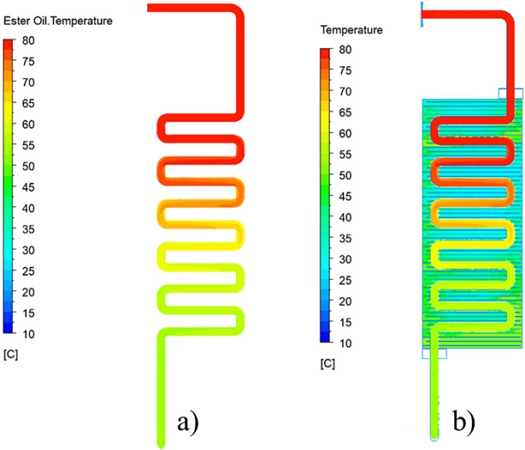
Temperature distribution in a) oil circulation pipe and b) full system
3.2 Water‑Side Heat Absorption and Entropy Generation
Figure 6 presents the temperature and entropy distributions in the heat exchanger equipped with horizontal fins. Cooling water enters the exchanger at approximately 20°C and efficiently absorbs heat from the ester oil, reaching outlet temperatures of up to 50°C. This confirms effective utilization of the water-side heat capacity and underscores the advantage of the counter-flow configuration, which maintains a strong temperature gradient along the exchanger length and enhances overall cooling effectiveness. The static entropy generation is evaluated as an indicator of thermodynamic irreversibility.
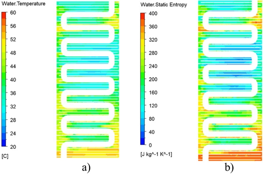
a) Water temperature contour and b) water entropy contour in the heat exchanger
Entropy values range from approximately 80 to 400 J.kg⁻1.K-1, with concentrations near fin surfaces and regions of steep temperature gradients and velocity shear. The relatively smooth entropy distribution demonstrates that the heat transfer enhancement achieved by fins does not introduce excessive irreversibility, avoiding severe turbulence or flow separation. This indicates that the exchanger design achieves a favorable balance between heat transfer augmentation and thermodynamic efficiency.
3.3 Effect of oil inlet temperature
Figures 7 and 8 illustrate the thermal and energetic behavior of the heat exchanger under varying oil inlet temperatures. As the measurement moves from inlet to outlet, both temperature and enthalpy decrease progressively, confirming continuous heat transfer from the hot ester oil to the cooling water. The enthalpy drops in the ester oil pipes were 130, 96, 80, and 63 kJ/kg with the oil inlet temperatures of 100, 80, 70, and 60°C. These results demonstrate that higher inlet oil temperatures increase the thermal driving potential, resulting in larger energy removal per unit mass of oil and confirming the exchanger’s robust performance under fluctuating thermal loads. Physically, the nearly parallel slopes of the enthalpy curves across different inlet conditions indicate that the heat exchanger geometry configuration provides uniform energy extraction regardless of inlet temperature. Higher inlet conditions enhance the thermal gradient and increase the rate of energy removal, but the outlet temperature approaches the water‑side limit, showing that cooling effectiveness is ultimately bounded by the available surface area and flow configuration. This consistency is particularly important for transformer cooling applications, where inlet oil temperatures can fluctuate significantly under variable wind turbine loads.
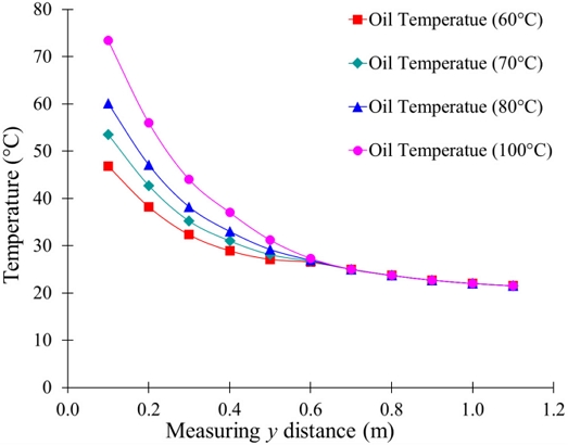
Temperature distribution in the heat exchanger with inlet oil temperature
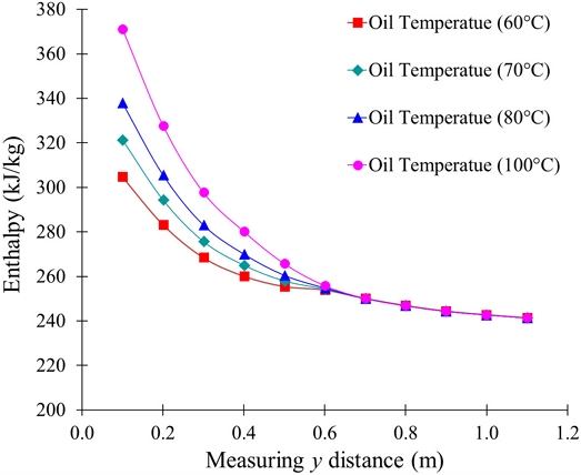
Enthalpy distribution in the heat exchanger with inlet oil temperature
3.4 Effect of Water Mass Flow Rate
Figure 9 shows the temperature and enthalpy distributions along the length of the heat exchanger under varying water mass flow rates. Both temperature and enthalpy progressively decrease, confirming continuous energy transfer from the hot ester oil to the cooling water. Figure 10 illustrates the influence of water mass flow rate on the temperature and enthalpy of the ester oil at y = 1.1 m. The outlet oil temperature and enthalpy are stabilized at 21°C and 241 kJ/kg, respectively, regardless of further increases in water flow. This indicates that once the convective resistance on the water side is minimized, additional flow provides diminishing thermal benefits.
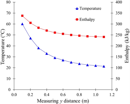
Temperature and enthalpy distribution in the heat exchanger with water mass flow rate
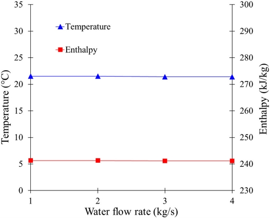
Temperature and enthalpy distribution in the heat exchanger with water mass flow rate at y=1.1 m
3.5 Effect of Oil Mass Flow Rate
Figures 11 and 12 illustrate the variation of temperature and enthalpy along the heat exchanger for different oil mass flow rates. In all cases, temperature and enthalpy decreased along the measuring distance, with a steep drop near the inlet followed by a gradual decline downstream. This behavior indicates that most of the heat transfer occurs in the entrance region. The influence of mass flow rate is also evident: lower flow rates (0.5 kg/s) show a more rapid reduction in temperature and enthalpy, reflecting stronger heat transfer due to longer residence time. In contrast, higher flow rates (4 kg/s) exhibit slower variations, indicating reduced heat-transfer effectiveness per unit mass as the fluid passes through the heat exchanger.
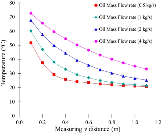
Temperature distribution in the heat exchanger with oil mass flow rate
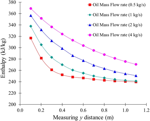
Enthalpy distribution in the heat exchanger with oil mass flow rate
Figure 13 complements these results by showing the variation of temperature and enthalpy with oil mass flow rate at a y = 1.1 m. Both temperature and enthalpy increase with increasing flow rate, confirming that less heat is removed from the fluid at higher flow rates. It demonstrates that while the heat exchanger continuously removes thermal energy along the flow direction, its effectiveness strongly depends on the oil mass flow rate. The lower flow rates enhance heat transfer and lead to better cooling effect, whereas higher flow rates result in higher outlet temperature and energy retention, highlighting a critical trade-off in heat exchanger performance and design.
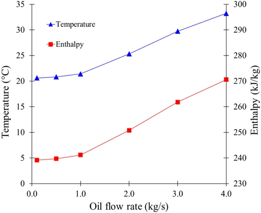
Temperature and enthalpy distribution in the heat exchanger with oil mass flow rate at y=1.1 m
4. Conclusion
This work presented the design and CFD-based analysis of a compact ester oil–water fin-type heat exchanger for large-capacity offshore wind turbine transformers. The results confirmed that the horizontal fin configuration heat exchanger provides effective cooling, reducing oil outlet temperatures to safe operating levels and thereby extending transformer service life. Table 4 summarizes the quantitative CFD simulation results of the compact fin-type ester oil–water heat exchanger under various operating conditions. Parametric studies revealed that the water-to-oil mass flow rate ratio is the dominant factor governing cooling capacity, while oil mass flow rate primarily controls outlet temperature. The higher oil inlet temperatures increase the thermal driving potential—resulting in progressive enthalpy drops up to 149.08 kJ/kg at a 100°C inlet—while nearly parallel enthalpy slopes confirm uniform energy extraction across varying operational loads. The lower oil flow rates maximize thermal performance by increasing residence time, whereas increasing water mass flow rate yields diminishing thermal benefits once water-side convective resistance is minimized, stabilizing the outlet oil temperature and enthalpy at approximately 21.5°C and 241 kJ/kg. The design achieved enhanced heat transfer without excessive entropy generation, ensuring both thermal effectiveness and thermodynamic efficiency. These findings offer practical guidance for developing reliable, energy-efficient cooling systems tailored to the unique thermophysical properties of ester oils, supporting the safe and sustainable operation of modern offshore wind power infrastructure.
Summarize table of quantitative performance of heat exchanger
Nomenclature
| ρ : | Density of ester oil, kg/m3 |
| κ : | Thermal conductivity of ester oil, W/m2/K |
| μ : | dynamic viscosity of ester oil, Pa. s |
| Cp : | specific heat capacity, J/kg/K |
| Q : | heat transfer rate, W |
| m : | mass flow rate, kg/s |
| Tin : | inlet temperature, K |
| Tout : | outlet temperature, K |
Acknowledgments
This work was supported by the Korea Institute of Energy Technology Evaluation and Planning (KETEP) and the Ministry of Climate, Energy & Environment (MCEE) of the Republic of Korea (No. RS-2024-00512917).
References
-
Susa, D., Lehtonen, M., and Nordman, H., 2005, “Dynamic thermal modelling of power transformers”, IEEE Trans. Power Deliv., 20(1), 197-204.
[https://doi.org/10.1109/TPWRD.2004.835255]

-
Saha, T.K., 2003, “Review of modern diagnostic techniques for assessing insulation condition in aged transformers”, IEEE Trans. Dielectr. Electr. Insul., 10(5), 903-917.
[https://doi.org/10.1109/TDEI.2003.1237337]
-
Abu-Siada, A., and Islam, S., 2012, “A new approach to identify power transformer criticality and asset management decision based on dissolved gas-in-oil analysis”, IEEE Trans. Dielectr. Electr. Insul., 19(3), 1007-1012.
[https://doi.org/10.1109/TDEI.2012.6215106]
- International Electrotechnical Commission (IEC), 2018, “Power Transformers - Part 7: Loading Guide for Oil Immersed Power Transformers”, IEC 60076-7.
- Versteeg, H.K., and Malalasekera, W., 2007, “An introduction to computational fluid dynamics the finite volume method”, 2nd ed., Pearson Education Limited.
-
Mehta, D.M., Kundu, P., Chowdhury, A., Lakhiani, V.K., and Jhala, A.S., 2016, “A review of critical evaluation of natural ester vis-a-vis mineral oil insulating liquid for use in transformers: Part II”, IEEE Trans. Dielectr. Electr. Insul., 23(3), 1705-1712.
[https://doi.org/10.1109/TDEI.2016.005371]
- Baburao, K., and Nanavati, N., 2017, “Environmentally Friendly Fire Safe Superior Synthetic Ester Dielectric Fluids for Green Transformers”, Power Research-A Journal of CPRI, 13(4), 569-576.
-
Tenbohlen, S., and Koch, M., 2010, “Aging performance and moisture solubility of vegetable oils for power transformers”, IEEE Trans. Power Deliv., 25(2), 825-830.
[https://doi.org/10.1109/TPWRD.2009.2034747]
- Incropera, F.P., DeWitt, D.P., Bergman, T.L., and Lavine, A.S., 1996, “Fundamentals of heat and mass transfer, 6th ed., John Wiley & Sons.
- Kakaç, S., Liu, H., and Pramuanjaroenkij, A., 2002, “Heat exchangers: selection, rating, and thermal design”, 2nd ed., CRC Press, Boca Raton.
-
Menter, F., 1994, “Two-equation eddy-viscosity turbulence models for engineering applications”, AIAA J., 32(8), 1598-1605.
[https://doi.org/10.2514/3.12149]
- Bejan, A., 1995, “Entropy generation minimization: the method of thermodynamic optimization of finite-size systems and finite-time processes”, CRC Press, Boca Raton.
-
Sekulic, D.P., and Shah, R.K., 2023, “Fundamentals of heat exchanger design”, 2nd ed., John Wiley & Sons.
[https://doi.org/10.1002/9781119883296]
-
Srivastava, M., Goyal, S.K., and Saraswat, A., 2021, “Ester oil as an alternative to mineral transformer insulating liquid”, Mater. Today: Proc., 43, 2850-2854.
[https://doi.org/10.1016/j.matpr.2021.01.066]
-
Sheffield, J.W., Wood, R.A., and Sauer Jr, H.J., 1989, “Experimental investigation of thermal conductance of finned tube contacts”, Exp. Therm. Fluid Sci., 2(1), 107-121.
[https://doi.org/10.1016/0894-1777(89)90055-1]